Download BOM for Single-Gas Op-Vent with V2.5 PCB
Click the button above to download the BOM for a single-gas Op-Vent with the Version 2.5 PCB. This Excel spreadsheet has three tabs:
-
Pneumatics: lists the components in the pneumatic path.
-
PCB: lists the components assembed on the microcontroller PCB
-
Other: lists the balance of the system including the enclosure, LCD, etc…
Prices, where shown, reflect single-unit quantity as of June 2020. Substantially lower prices are available in volume.
The design includes a custom adapter that converts from male 3/8 pipe thread to two male 22mm ISO 5356 fittings and includes a pressure relief valve. If this adapter is not available it can be replaced by standard pipe fittings (but a 3/4 inch hose barb does not quite fit 22mm ISO hoses so a shim is required.) Press the button below to download the CAD file for the custom fitting. Items 29-33 in the “Other” tab of the BOM are the components used to realize the pressure-relief valve with this fitting.
Download CAD file for custom adapter Download STL files for oxygen blending adapters
Click the button below to download the BOM for the Version 3.0 PCB. This BOM replaces the PCB tab of the single-gas BOM above for systems using the V3.0 PCB. A second tab shows the BOM for the mating connectors. The BOM lists the components for a minimum PCB first (items 1-30) and then components for optional functions such as battery backup, alarm relay, RS232, and alternative pressure sensors.
For a ventilator with oxygen blending (which must use the V3.0 PCB), use the V3.0 PCB BOM and the other two tabs of the single-gas BOM. Duplicate the three main components of the pneumatic path (items 1-3) along with the pipe fittings needed to connect these together and to combine the outputs of the two flow meters. See the photo in the Blending page for details.
 Figure B1: Single-gas Op-Vent packaged in three-sided aluminum enclosure
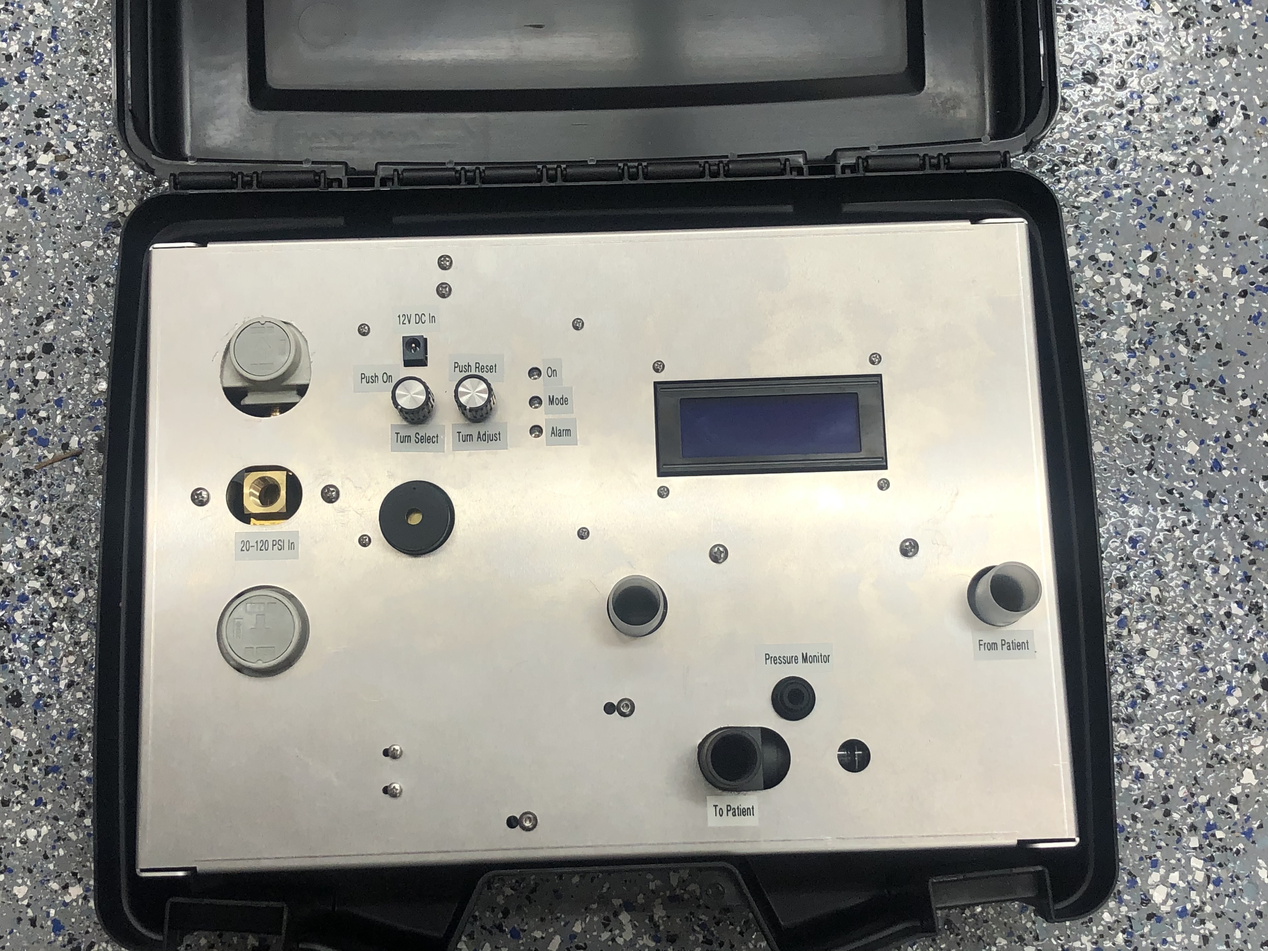
Figure B1 shows a single-gas Op-Vent packaged in an aluminum enclosure. This enclosure is item 1 in the “other” tab of the BOM, labeled “Base”. The enclosure is designed to be mounted in a carrying case (item 12 in the “other” tab of the BOM) as shown in Figure B2.
 Figure B2: Enclosure in carrying case.
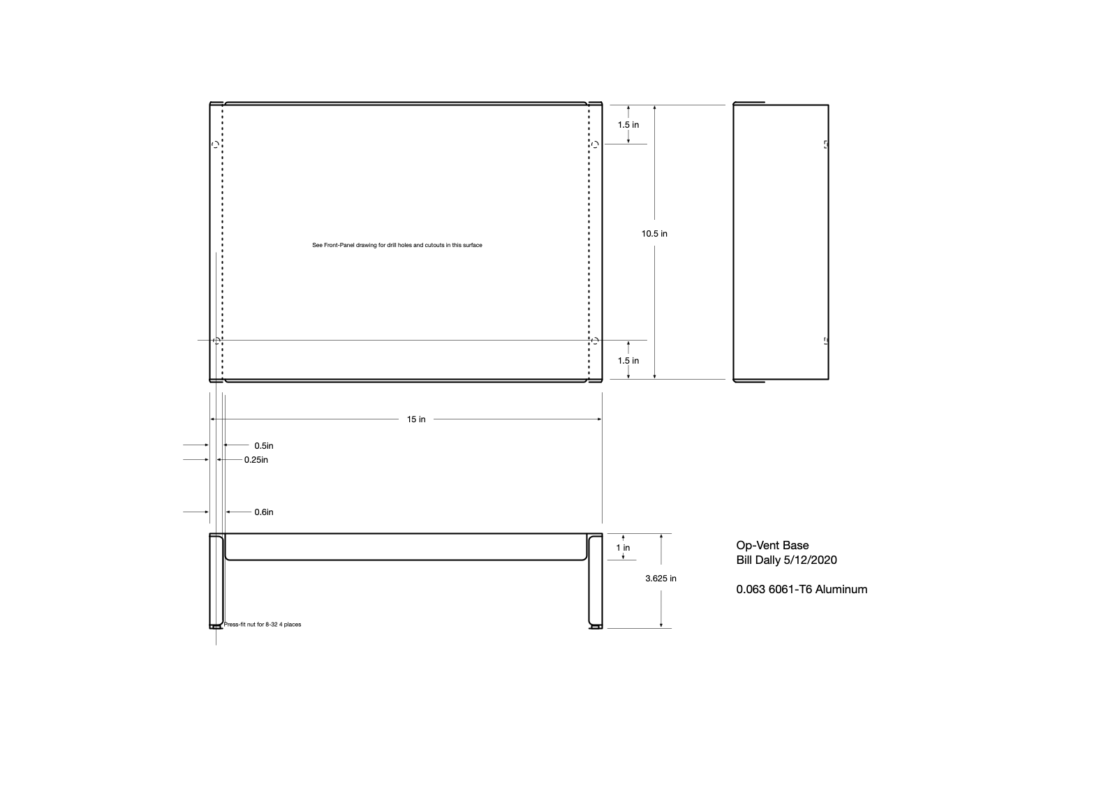
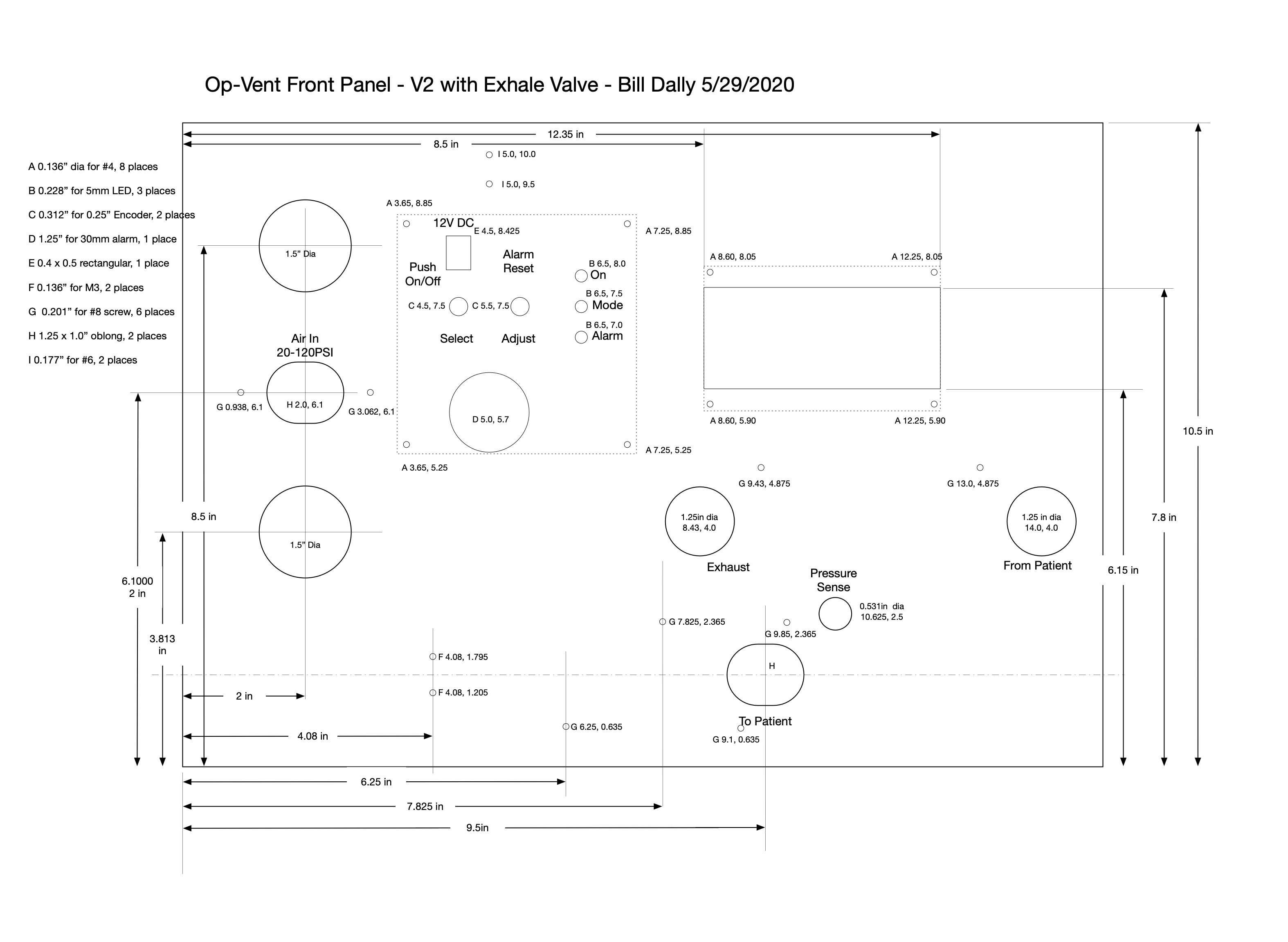
Figures B3 and B4 show drawings for the enclosure and detail of the front-panel holes and cutouts respectively.
 Figure B3: Drawing of Base.
 Figure B4: Detail of Front Panel.