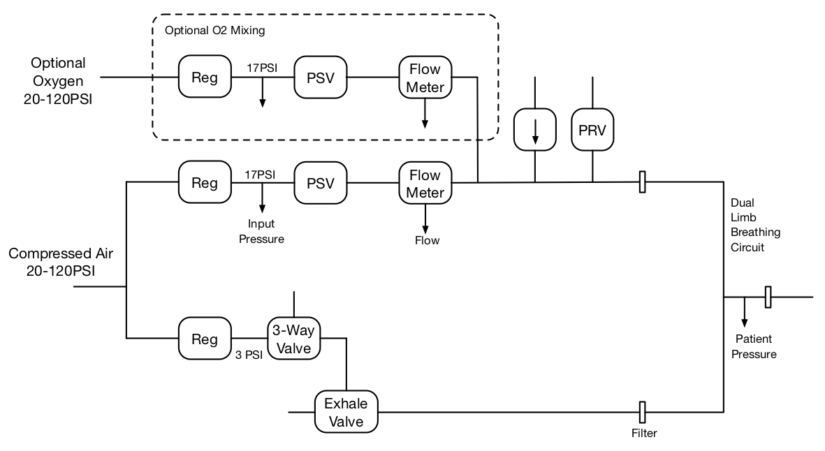
 Figure B1: Pneumatic block diagram showing optional oxygen path.
Op-Vent can be configured either as a single-gas unit or as an oxygen blending unit as shown in Figure 1. The current PCB design (V3.0) and the current software (Version 3.3 dated 9/6/2020) support both versions. When building the software, the constant BLEND should be set to 0 for single gas and 1 for blending.
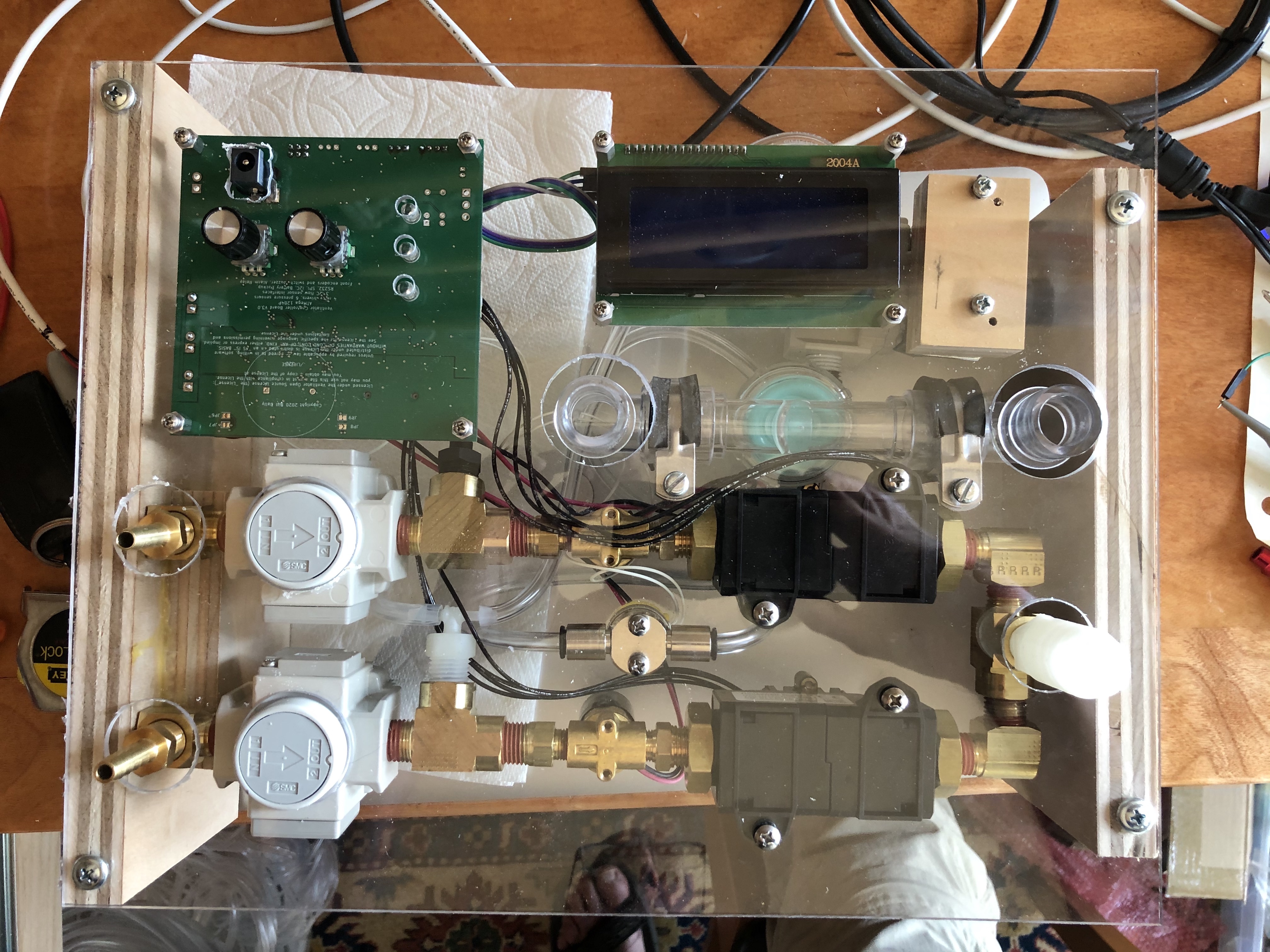
 Figure B2: Oxygen Blending Op-Vent Front View.
Figure 2 shows a prototype of a blending Op-Vent. The inspiratory pneumatic path consists of two copies of the single-gas pneumatic path (regulator, proportional solenoid valve, and flow meter) one each for air and oxygen. In the figure, the lower path is for air and the upper path is for oxygen. These two paths are combined in a tee that feeds the connector for the inspiratory limb connecting to the patient.
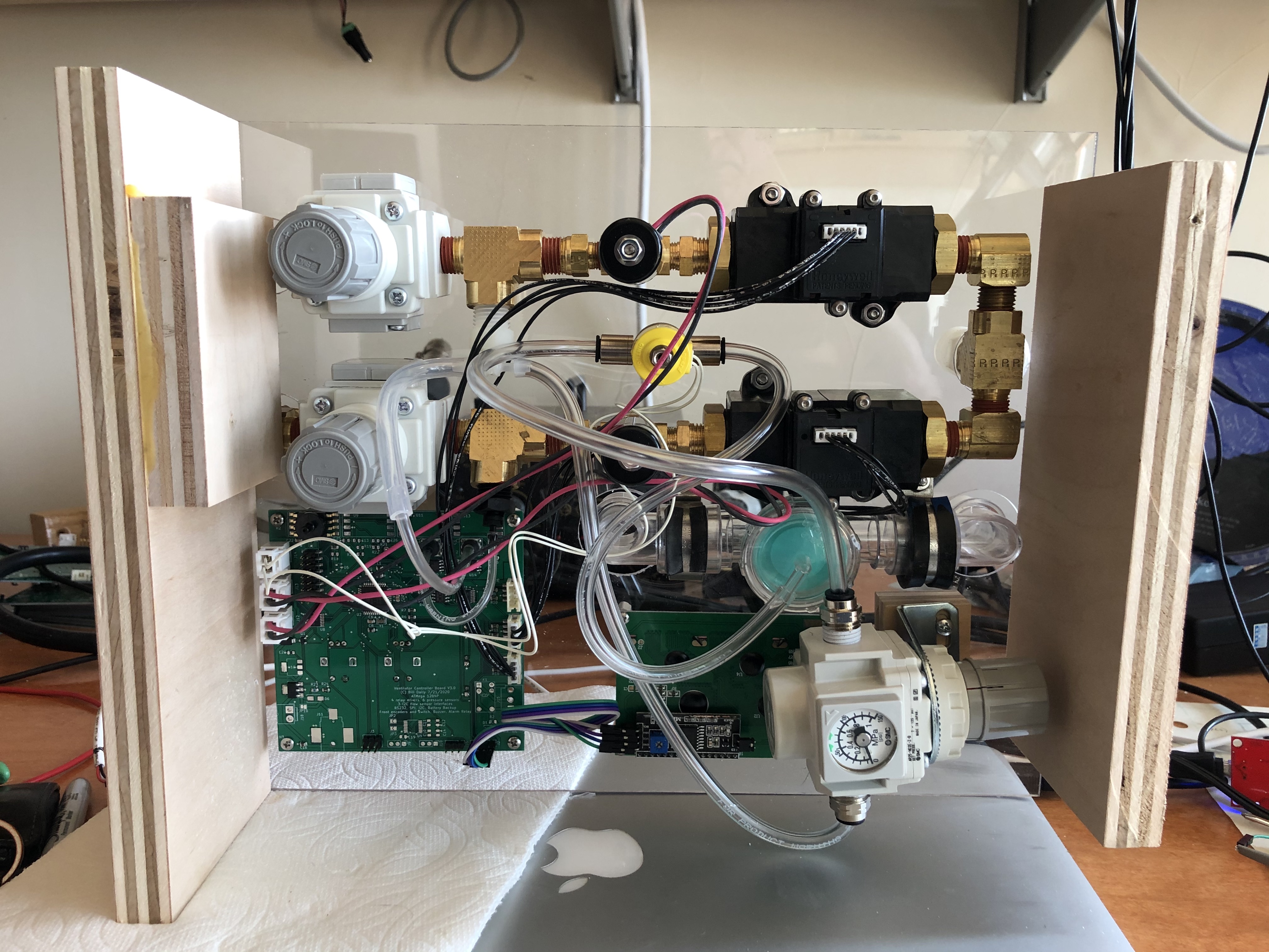
 Figure B3: Oxygen Blending Op-Vent Back View.
The unit has a single expiratory path (regulator, three-way solenoid valve, and exhalation valve) that is identical to the single-gas unit. Figure 3 shows the back side of the blending Op-vent prototype. The regulator at the lower right regulates air pressure to the three-way solenoid valve (yellow cap) that controls the expiratory valve.
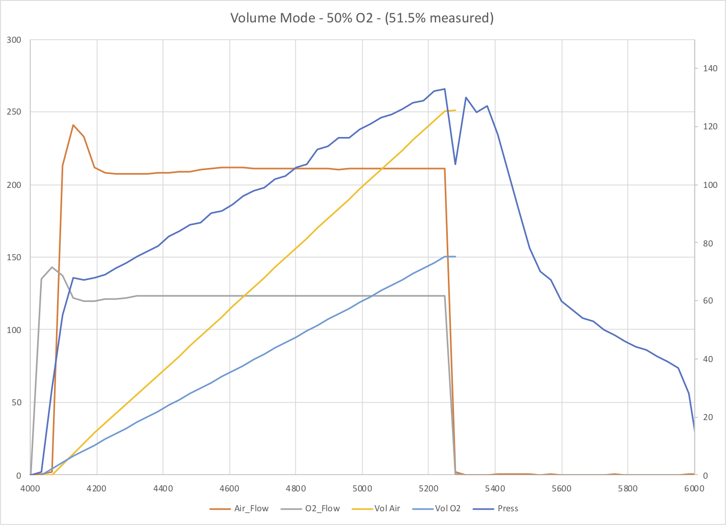
 Figure B4: Volume-Mode Operation with Oxygen Blending.
Figure 4 shows measured flow, pressure, and volume for a single breath in Volume Mode with FIO2 set at 50%. The air and oxygen flows are rectangular waveforms with amplitudes set to achieve the desired FIO2.
A set of pneumatic fittings have been designed for the blending Op-Vent. These include output fittings for the air and O2 paths. The air fitting includes a pressure relief valve and an ISO 5356 fitting to connect to the inspiratory limb of the patient circuit. The O2 fitting includes an ISO 5356 fitting to connect to a one-way valve. Both fittings have a 1/2-inch barb to connect the two paths together with half-inch hose.
The following STL files are available at the link below
| File | Description |
|---|---|
| air_fitting.stl | Air-path output fitting: 3/8in G-Thread, ISO 5356 22mm, PRV, 1/2in barb, mounting tab |
| air_fitting_w_barb.stl | Above with additional 1/8in hose barb for pressure monitor |
| o2_fitting.stl | O2-path output fitting: 3/8in G-Thread, ISO 5356 22mm, 1/2in barb |
| washer3_2.stl | washer to seal PRV |
| washer2.stl | cup washer to hold PRV spring |
| n18g38.stl | Connect PSV to Flow meter: 1/8in NPT to 3/8in G-Thread |
| n18n14.stl | Connect regulator to PSV in air path: 1/4in NPT to 1/8in NPT with 2 1/8in barbs |
| n18n14a.stl | Connect regulator to PSV in O2 path:1/4in NPT to 1/8in NPT with one 1/8in barb |
The n18g38 and n18n14 fittings can be used in place of standard pipe fittings to connect the air and O2 paths. They have tha advantage of being smaller than standard fittings and result in a path this is about 10in long.
Download STL Files for Blending Op-Vent Fittings
The fittings require the following standard hardware:
| Component | Quantity | Description | Link |
|---|---|---|---|
| 16.5mm ID x 2mm O-Ring | 4 | Seal fittings to flow meters | https://www.mcmaster.com/9262K855 |
| 19mm ID x 1mm O-Ring | 1 | PRV outer seal | https://www.mcmaster.com/9262K617 |
| 6mm ID x 1mm O-Ring | 1 | PRV inner seal | https://www.mcmaster.com/9262K103 |
| M3-0.5 x 12mm Screw | 1 | PRV clamp | https://www.mcmaster.com/91292A114 |
| Spring 0.75in x .36in | 1 | PRV spring | https://www.mcmaster.com/9001T25 |