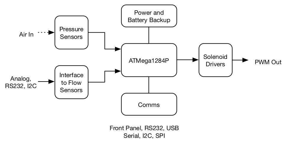
 Figure 5: Microcontroller block diagram.
The microcontroller modulates the solenoid valve to produce the required flow vs time profile – either open-loop or under closed loop control. It also presents a user interface to allow parameters of the waveform (mode, tidal volume, respiratory rate, i:e ratio, FIO2, set PEEP, and max pressure) to be set. A block diagram of the microcontroller is shown in Figure 5.
More details on the current version of the board and a download link for Gerber files and KiCAD source files for the microcontroller are available here.
The heart of the system is an ATMega1284P microcontroller (Version 1 used an ATMega328PB). It includes A/D converters to read from various sensors, timer/counters to keep timing and modulate PWM waveforms for the solenoids, and a variety of communication interfaces.
The solenoid driver amplifies the 50mA output from the microcontroller to a 500mA or 1A solenoid drive with free-wheeling diodes. Four solenoid channels are provided, two are driven from microcontroller PWM channels for proportional valves and two are driven by digital outputs for on/off valves. The fourth solenoid channel drives the 110dB audio alarm on the board.
Power to the board comes from a 12V input. A resistive trickle charger and diode allow a 12V battery to be used for battery backup. If an external battery is connected to this circuit, an inline switch must be included. Otherwise the battery will be drained whenever the unit is not connected to input power.
To add feedback control interfaces are provided for up to three Honeywell flow sensors. (Versions of the board through V2.5 also provided input for a Siargo flow sensor.) A differential pressure sensor can also be used to read flow from a Venturi tube.
Locations on the controller board are provided for six pressure sensors. Up to four NXP pressure sensors are used to monitor low pressures (up to 10kPa) for monitoring pressure at the patient and at various points in the ventilator. Differential versions of these sensors can also be used to measure flow using a Venturi tube. Up to two Honeywell pressure sensors are used to monitor the higher input pressures (up to 30 PSI) after the pressure regulators. These are used primarily to provide low input pressure alarms.
Communication interfaces are provided for RS232, 3.3V serial, I2C, and SPI. An LCD display can be attached via I2C. The front panel can be remotely operated via RS232 – to move the control out of the ICU. A 110dB audio transducer is provided for alarms. Versions of the board through V2.5 also provided a USB interface.
The board includes a front-panel interface with two rotary encoders (one selects a parameter, the other adjusts the value of that parameter) Two push-buttons integrated with the rotary encoders turn the ventilator on and off and clear alarms.
A 4-line by 20-character off-the-shelf LCD display that connects to the board via an I2C (two-wire) interface provides data to the user - providing the output part of the self-contained user interface.