Op-Vent is controlled by about 6,000 lines of “C” code written for the ATMega1284p microcontroller. The software uses the “Crosspack AVR” development environment and libraries. The latest version of the code will run on either a single-gas or a blending Op-Vent and will run on both Version 3.0 and Version 2.5 of the Microcontroller PCB. To download the software, click here.
The main modules of the ventilator software are shown in Figure 6. The control software is invoked by a real-time clock (RTC) interrupt every “tick” ms (currently tick = 1ms). This software times the inhale/exhale phases, modulates the PSV(s) to set the flow or pressure– using PID control –, controls the exhalation valve to provide electronic PEEP, and runs a data logger to capture flow, pressure, or error traces for analysis. With appropriate sensors installed (flow or pressure), the control module uses closed-loop control to regulate both flow and pressure.
The regulation depends on the mode. In volume control or volume assist mode, flow is regulated until a maximum pressure limit is reached and then pressure is regulated to prevent pressure from increasing further. In pressure control or pressure assist mode pressure is regulated until the maximum volume limit is reached at which point flow is curtailed. In all modes except pressure assist mode the end of the inspiratory period is timed – according to the set RR and I:E ratio. In pressure assist mode the inspiratory period ends when the flow drops to a preset fraction of the peak flow with steady-state pressure.
An alarm module monitors system variables and raises alarms. Alarms are currently supported for: disconnect, high pressure, high and low minute volume, apnea, low input voltage, low input air pressure, and low input oxygen pressure.
Sensor independent flow functions are in the flow module. It exports
routines set_flow(flow) and get_flow(flow) with flow in mL per
second. It scales variables appropriately and uses a
piece-wise-linear calibration table to convert flow to PWM settings
for the valve. It includes routines to characterize the valve and
build the flow to PWM table. This table is stored in the I2C EEPROM
and loaded at power up.
Sensor drivers, one per sensor type, handle sensor specific issues. Peripheral drivers, one per peripheral (serial, adc, pwm, timer, two-wire) handle peripheral interfacing.
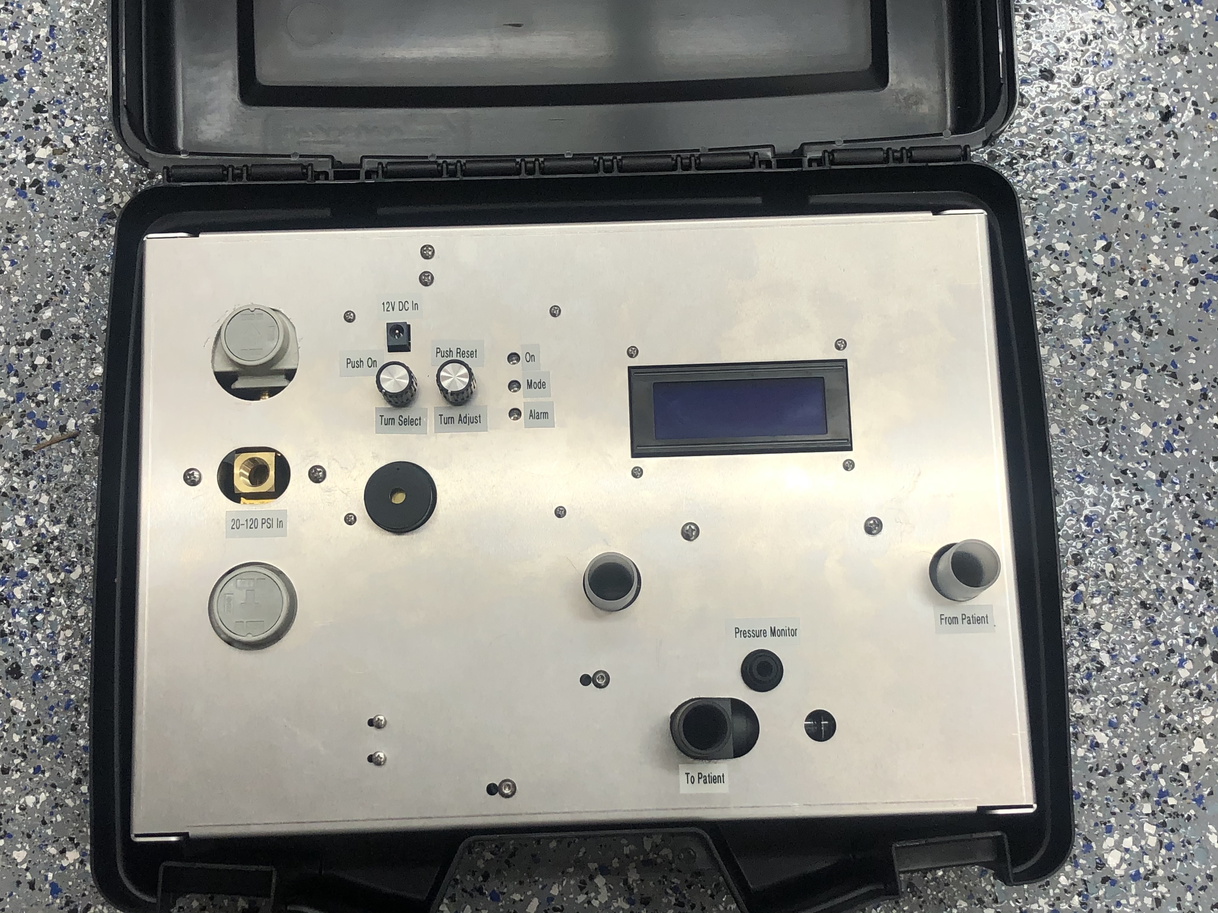
The UI provides a user interface to set parameters, turn the ventilator on and off, and monitor operation. Two UIs are provided. Two rotary shaft encoders, a toggle switch, and a four-line LCD display (Figure 11) provide an intuitive front-panel interface. The left encoder selects a parameter (mode, tidal volume, respiratory rate, i:e ratio, maximum pressure, FIO2, PEEP, etc…) and the right encoder selects the value for the selected parameter.
 Figure 7: Single-gas Op-Vent mounted in a travel case.
The two knobs and the LCD display provide the front-panel user interface.
A bi-directional serial interface provides a command-line user interface. The serial interface can be connected via 3.3V logic levels or RS232. (PCB versions up to V2.5 also supported USB.) This interface can be used to control the ventilator remotely – either via a laptop computer, or via a microcomputer control board that is programmed to be the “master” – monitoring its front-panel interface and sending commands via the serial line to the “slave” unit. This enables medical staff to place the front panel outside the ICU and make adjustments without using up PPE.
All settings that can be made from the front panel can also be made from the serial interface. In addition the serial interface has a data logger function that can record the pressure, air flow, and oxygen flow every 32ms.
 Figure 6: Software modules.