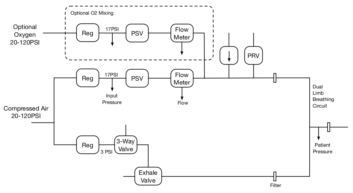
 Figure 2: Details of the ventilator pneumatics.
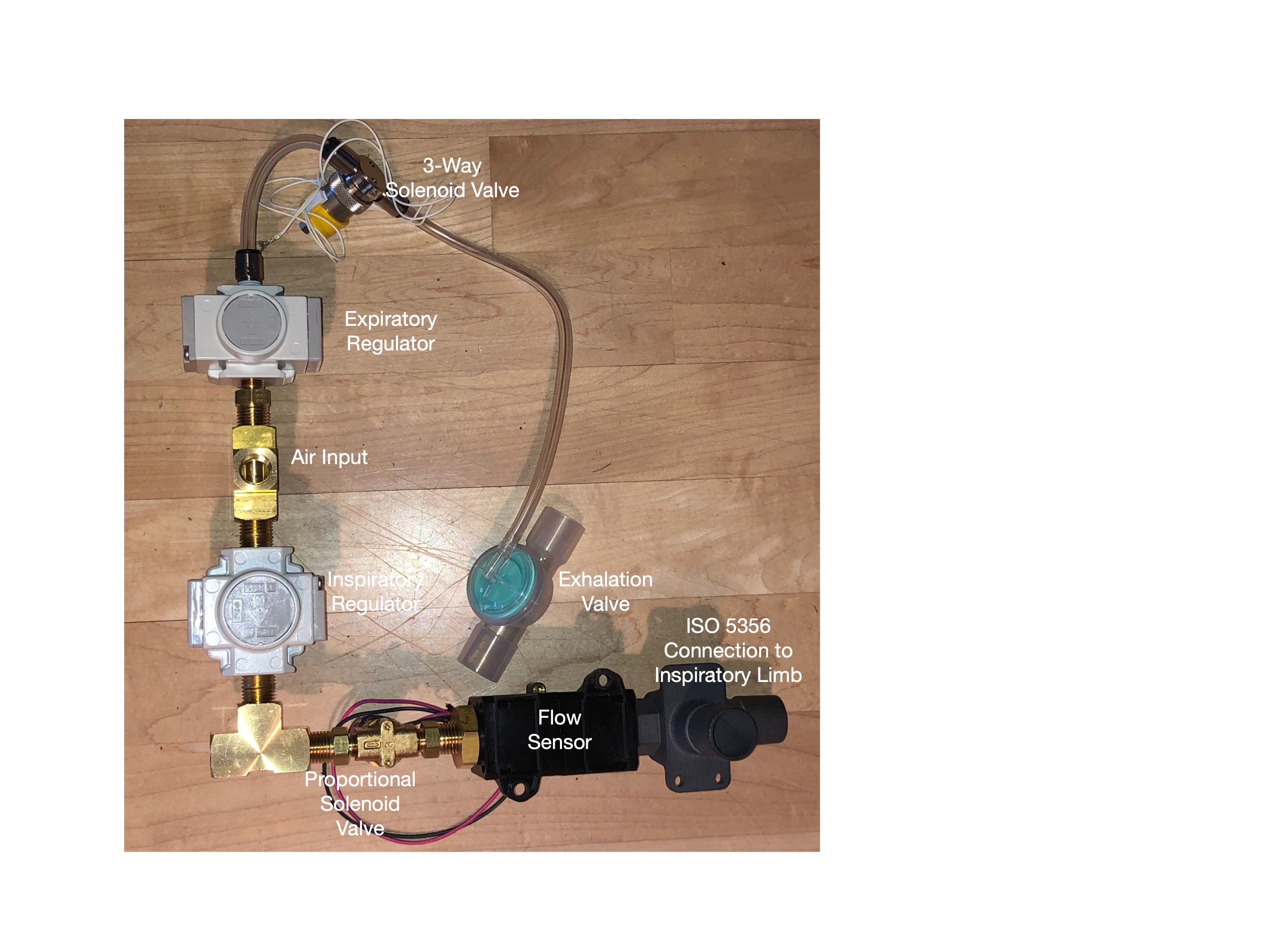
Figure 2 shows details of the ventilator pneumatics. Figure 3 is a photo of the components. The inspiratory path (top of drawing and bottom of photo) consists of a pressure regulator, a proportional solenoid valve, and a flow sensor. The pressure regulator regulates the input gas (20-120PSI) down to 17PSI. The solenoid valve takes this regulated pressure and generates a precise flow under control of a PWM (pulse-width modulated) electrical signal from the microcontroller. The flow sensor measures this flow and sends an (I2C) electrical signal back to the microcontroller to close the control loop. A custom fitting adapts the output of the flow sensor to a 22mm ISO 5356 fitting to connect to the inspiratory limb of the patient circuit. This fitting also provides pressure relief and one-way valves to protect the patient. A particle filter (not shown) is inserted between this fitting and the inspiratory limb to protect the ventilator from contamination. The components are plubmed together using standard NPT pipe fittings.
The expiratory path (bottom of drawing and top of drawing) consists of a pressure regulator, a three-way valve, and an exhalation valve. The pressure regulator further reduces the input pressure down to 3-6 PSI to avoid blowing out the diaphragm in the exhalation valve. The three way valve then directs this pressure to the exhale valve under control of the microcontroller to close the valve during the inspiratory period (and to provide Electronic PEEP). When pressure is applied, the exhale valve is closed. When pressure is released, the exhale valve opens.
 Figure 3: Photo of the ventilator pneumatics
Versions 1 and 2 of Op-Vent used the exhale valve from a BVM (Ambu-bag). Under certain conditions, the BVM valve did not open reliably making it hard for the patient to exhale which led to breath stacking. An explicitly controlled exhalation valve is required for reliable operation under all conditions.
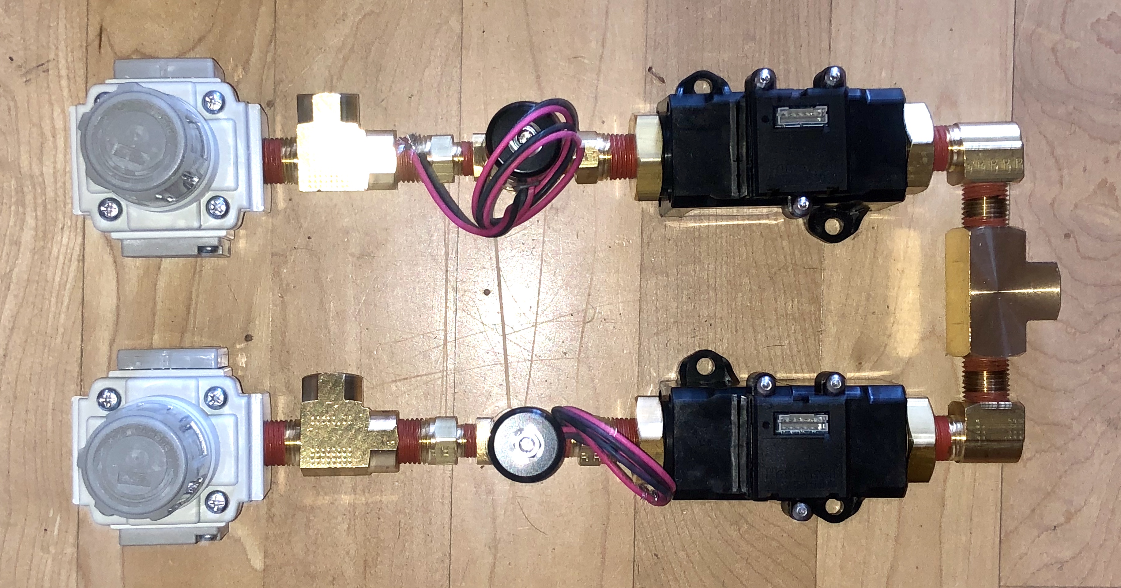
If an external oxygen blender is not available, Op-Vent can be configured to provide blending. A second regulator, solenoid valve, and flow meter are used to regulate the flow of oxygen (the very top path in Figure 2). The is dual inspiratory path is shown in Figure 4. The flow of oxygen is combined with the flow of air before the connection to the inspiratory limb of the patient circuit.
 Figure 4: Two copies of the inspiratory path are used to
provide oxygen blending within Op-Vent.