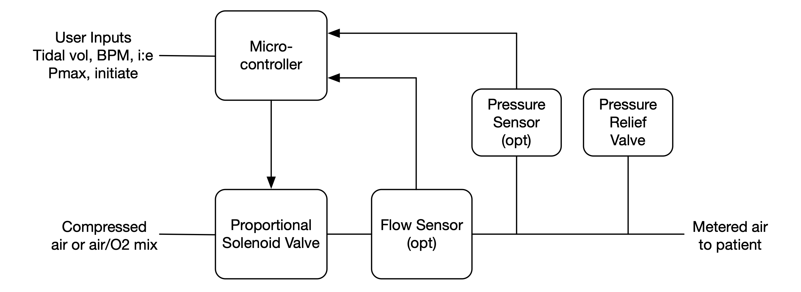
 Figure 1: Block diagram of a proportional solenoid valve ventilator. A microcontroller modulates a proportional solenoid valve to deliver metered air flow to the patient. Sensors can optionally be added to enable more accurate delivery via closed-loop control. The exhaust pathway, not shown, allows the patient to exhale to the atmosphere.
As shown in Figure 1, a simple ventilator can be built with just two off-the-shelf components: a proportional solenoid valve and a microcontroller (and a pressure relief valve for safety). The microcontroller modulates the valve to control the flow to the patient. In this simplest configuration the ventilator operates “open-loop”. With a calibrated sensor and either regulated input pressure or input pressure monitored with a sensor, flow rates accurate to +/- 20% can be achieved open loop.
Flow rates accurate to 1-5% (accuracy of flow sensor) can be achieved by adding a flow sensor and using feedback control to correct for valve inaccuracy and hysteresis. Adding a pressure sensor on the patient side allows controlling for maximum pressure and enables patient initiated breathing – by detecting a pressure drop. Adding a pressure sensor to the input side enables the microcontroller to correct for variations in input pressure. These pressure sensors also enable monitoring for alarm conditions.
Oxygen-air blending can be performed upstream of the ventilator of Figure 1. Alternatively blending can be performed in the unit by using separate solenoid valves on the air and oxygen inputs - at the expense of doubling the number of valves per unit.